Recently my father in law gave me this Yamaha A-S301 receiver (Manual). It came from a tennis club and didn't work anymore. He told me they once turned the volume up too loud and gave it too much power, so that it would likely be a power related fix. First, I turned it on to see if it would do anything. It turned on successfully, but after a few seconds you could hear a relais click and it would turn off. After this, the power LED starts blinking. Below you can see a video of this.
After some searching, I found the service manual, and it states the unit has a self-diagnostic function (page 18 of the manual). To start the self-diagnostic function, you need the remote. Unfortunately, I didn't have the remote, but I asked my father in law and he quickly found it.
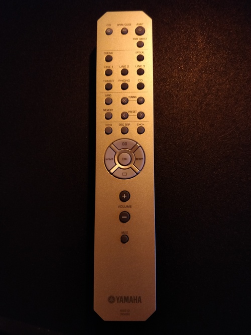
Remote
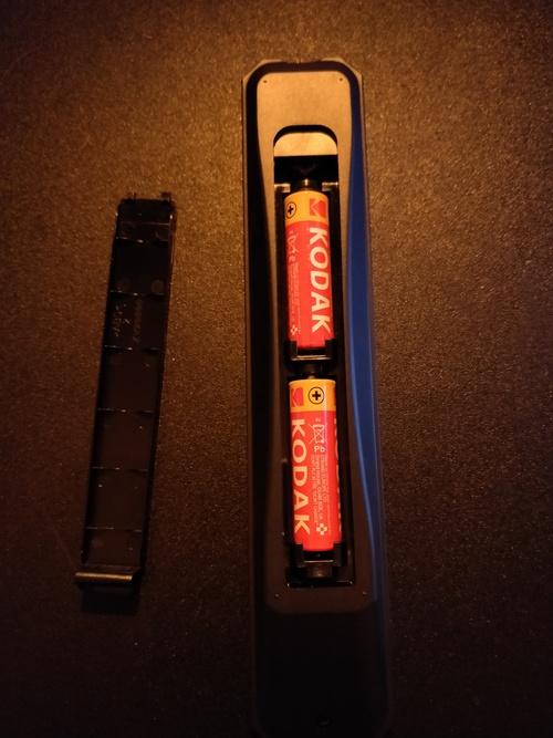
The remote is a RAS13 ZN04290 model, and it takes two AA batteries. Note: it has buttons to control a tuner (tuning and preset buttons), but the unit itself does not ship with AM or FM tuning capabilities.
Repairing
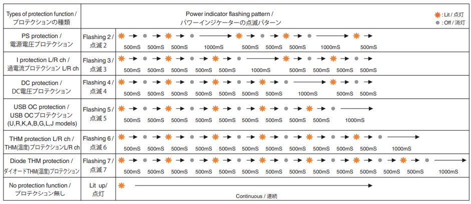
The service manual contains a figure indicating the different LED patterns and their meaning, visible in the image below:
The steps are as follows:
- Put the unit in stand-by mode by pressing the AMP key on the remote
- Press the Pure Direct button on the unit 6 times in less than 15 seconds.
- Press the AMP key on the remote
- Wait for the power LED to start blinking
- Count the number of blinks
- Look up the code in the table above
The light can be seen flashing 5 times before it waits 1000 ms and starts flashing again. According to the service manual, this means that the USB OC (Over Current) protection is initiated. The cause of this is that the USB power supply is overcurrent. When the unit starts the self-diagnostic function, the firmware version can be read from the INPUT selector. On this, the inputs COAXIAL, CD and PHONO are lit up. This indicates that the firmware version is V1101 = V13. The LINE 2 input is also lit up, indicating that the AUTO POWER STANDBY switch is turned on.
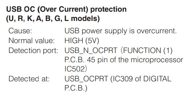
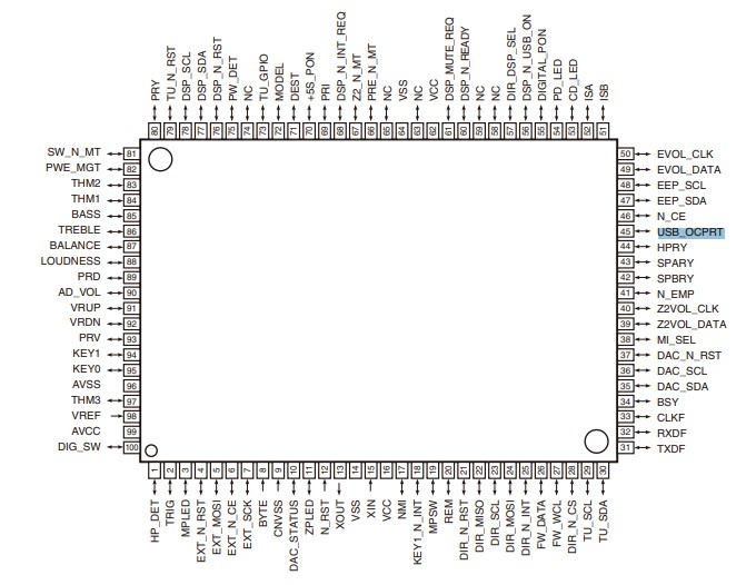
According to the service manual, the microprocessor of the unit (IC502, a R5F3640ECNFA 16 bit microcontroller) detects this at the USB_N_OCPRT port. This is pin 45 of the microprocessor.

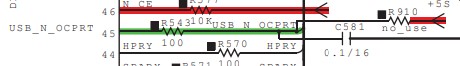
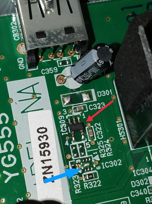
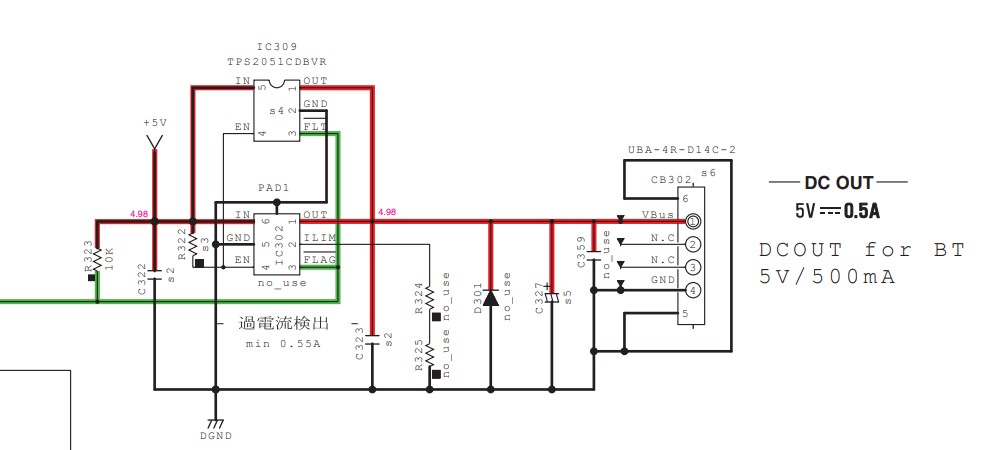
On the main circuit board (Function (1), page 40 of the service manual) this pin connects to connector CB517, which carries the signal to the DIGITAL (CB301) (page 39 of the service manual) board of the unit. There it connects to IC309, a TPS2051CDBVR USB power distribution switch. This is also described in the self-diagnostic description, at the Detected at line. When looking at the IC on the circuit board, it seems to be of the VBYQ variant.
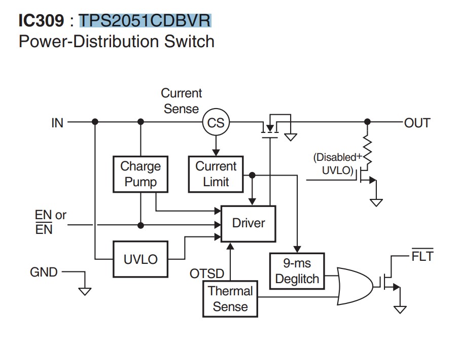
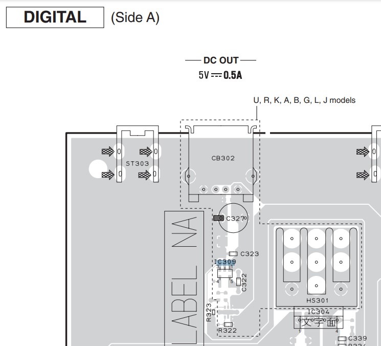
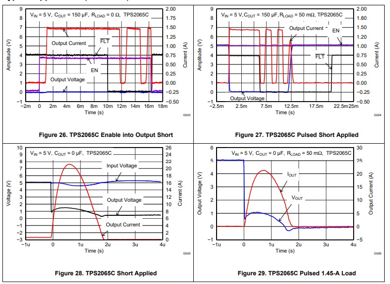
Looking at the datasheet of the power switch and the schematic of CB301, the culprit of the issue can either be the power switch itself, C322 or C323. The FLT pin (pin 4) is what triggers the fault mode and what is telling the microcontroller that the OC protection should be turned on. From the datasheet:
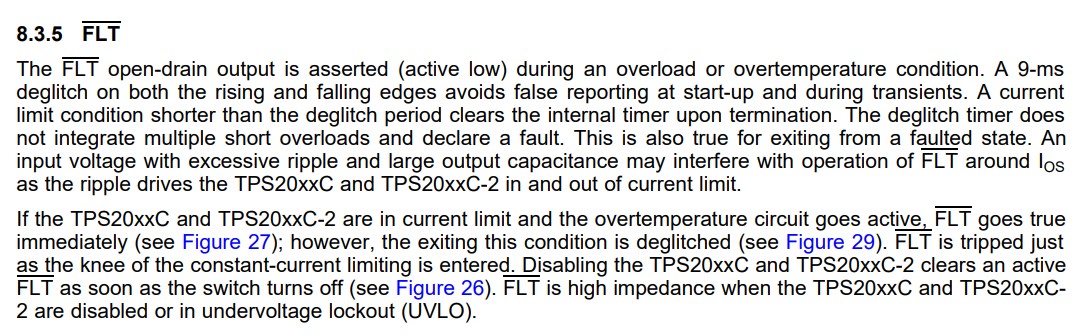
As shown in the figures on the datasheet, the FLT pin should go low when an overcurrent is happening, and will go high when this overcurrent is done, or when the enable pin is no longer driven high.
The unit being in constant USB OC mode means that an overcurrent is still happening. To check this, I measured the capacitance of C322 and C323. I also measured the voltages on all the pins of the USB power switch. They can be seen in the table below:
| Measurement | Value |
|---|---|
| GND to IN | 0.415V |
| GND to FLT | 0.415V |
| GND to EN | 0.410V |
| GND to OUT | 0.0V |
| IN to OUT | 0.0V |
These measurements were taken in the short period between the unit powering on and the power relay switching. I couldn't really measure a spark in the voltage on any of the pins, which might mean the power switch itself is broken.
When looking at the repair manual further, page 61 shows another schematic of how IC309 is connected. It shows that the IC is connected to another IC, IC302. On the circuit board picture above, it is pointed to by the blue arrow. However, I cannot find what it's function is in the service manual. It is not mentioned in the parts list and also not on the hardware schematic to the left of the circuit picture above.
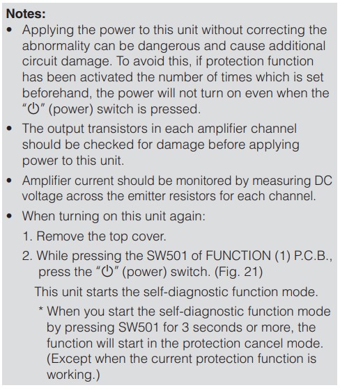
On page 29 of the service manual, a note is given stating that you can bypass the protection function by holding SW501 for 3 or more seconds when powering on the unit. With this, I can measure the voltage of the USB port.