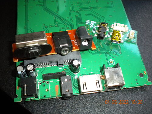
Before I could try to implement some analog filters using electronic components, I first had to get some
3.5mm jacks that I could use as inputs and outputs. Luckily, I had some spare hardware that I took from some
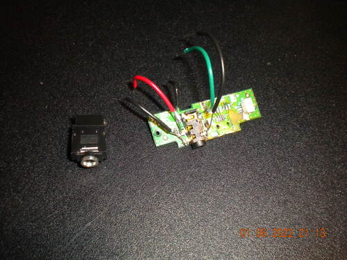
alarm clocks and multimedia devices that had audio jacks:
Fortunately, I was able to salvage 2 audio jacks, with one just having wires soldered to the end point, so I
can attach the board to something more easily. After doing some research, the wider jack is a PJ-307A, and the one with the gold is a PJ-327A.
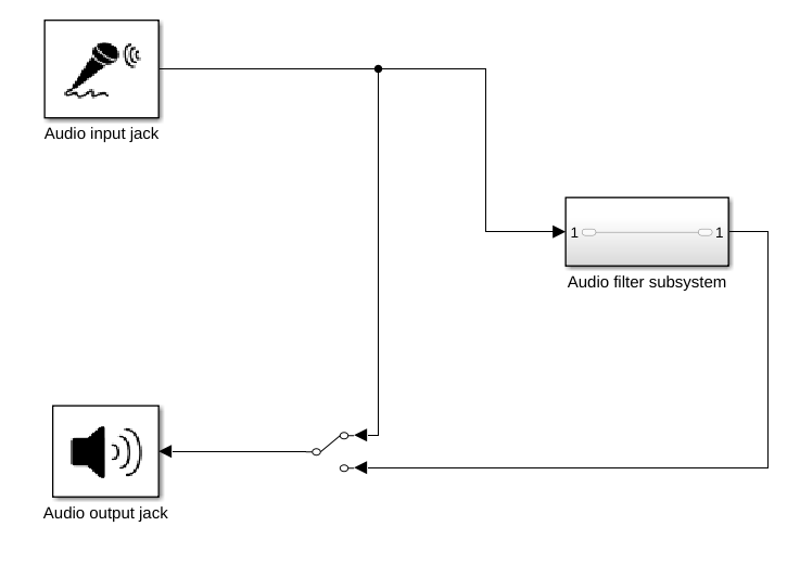
To be able to use all the audio filters, I have an idea of making a base board that has a slot that you can
slot the different audio filters into. It will have an audio input, an audio output, a slot for the audio
filters, and a switch to switch between listening to the audio filter and the original audio. I made a simple
Simulink DSP model of the base board (the Simulink file can be found here):
The slot for the filters will have 4 pins, one for the input audio, one for the input ground, one for the
output audio and one for the output ground.
The library also contains a report and a presentation about these subjects (both in Dutch).
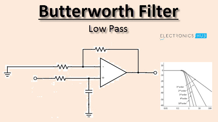
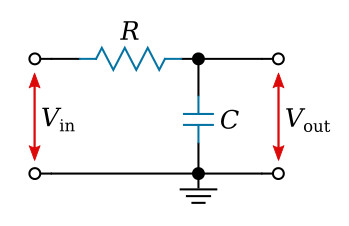
A helpful video on how RC lowpass filters work with speakers can be found here. To get started, I first decided to make the
simplest of lowpass filters, described in the 10th image above:
As described in the wikipedia article about lowpass filters, the cutoff frequency can be calculated
with the formula w0 = 1/RC. I will be using 2 resistors of 100 Ohm to get R = 200. Using a
capacitor of 33 uF (= 0.000033 F), we get:
f = 1 / (200 * 0.000033)
f = 1 / (0.0066)
f = 151.52 Hz
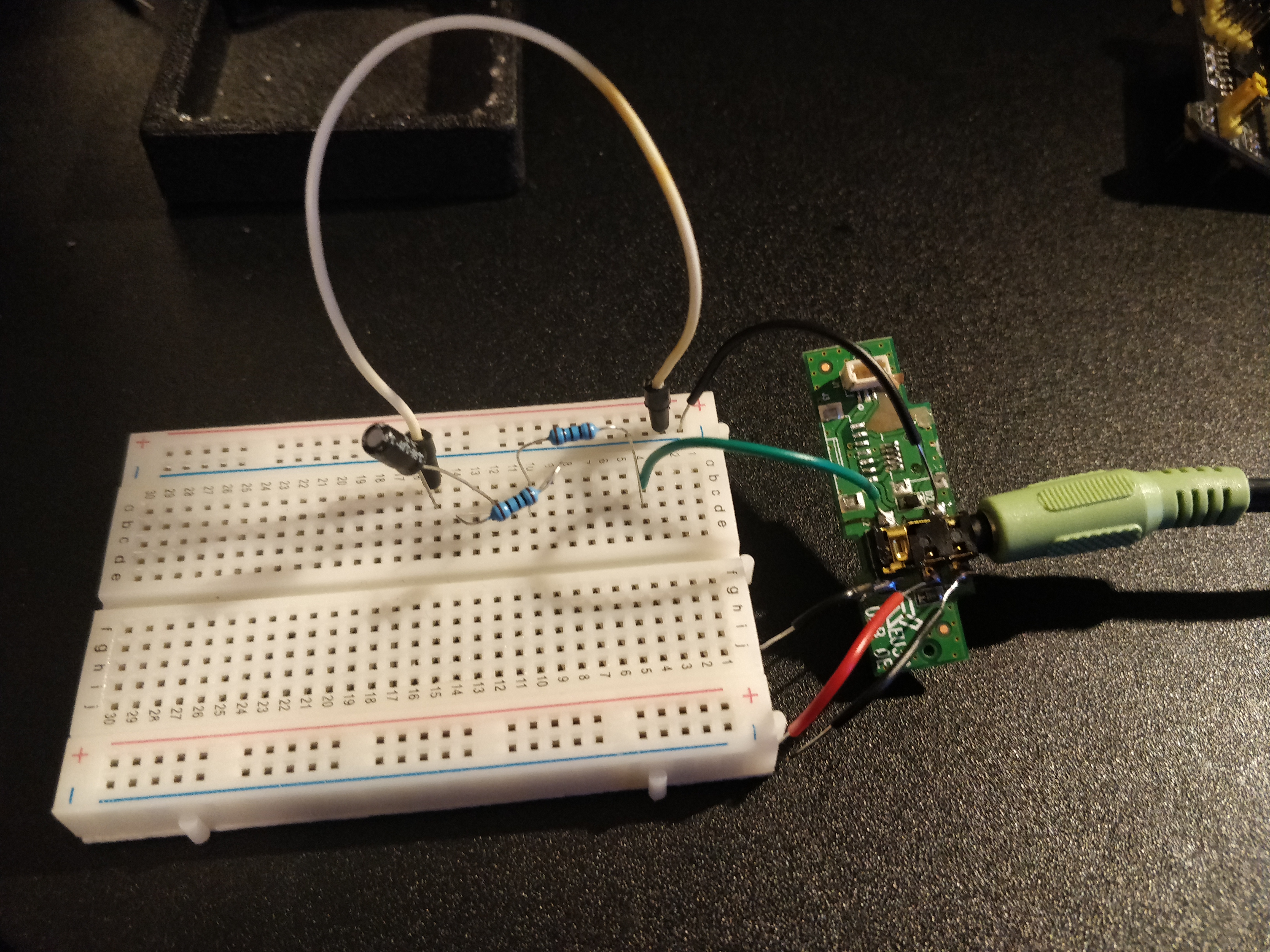
From this formula we get that our cutoff frequency will be 151.52 hertz. So, our values will be C = 33
uF for the capacitor and R = 200 Ohm for the resistor. I didn't
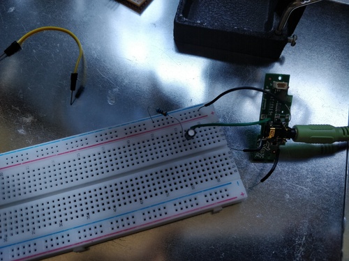
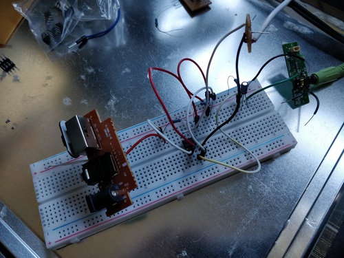
have a 200 Ohm resistor, so I used 2 100 Ohm resistors in series. I built the circuit on a breadboard, and it
looks like this:
Then, I used this video to determine how to
accurately measure the circuit. I connected the filter to my oscilloscope, placed my probes in the designated
positions and measured the signal while
doing a frequency sweep. I used my phone as a "signal generator" by connecting it to the audio jack with an
audio cable and using this
website, and generating a sweep from 1 to 5000 Hz over 10 seconds with 100% volume to check the response
of the filter, and the higher frequencies were filtered out. I also tested it with this tone generator and while manually changing the
tone. You can see the result in the video below. The top signal is the original audio signal and the bottom
signal is the filtered signal.
I also made a video of the filter working, you can hear the switching between the original signal that is
loud with a high frequency, and the filtered signal which is low with a high frequency:
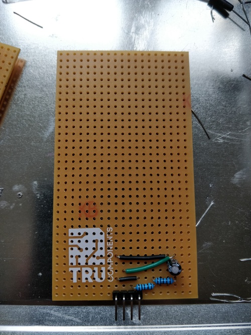
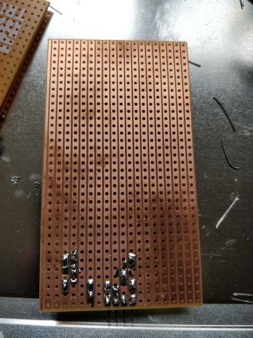
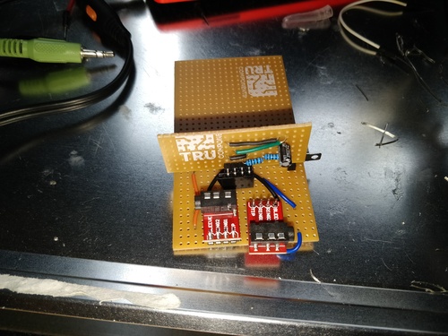
After verifying it worked, I began building the circuit on some stripboard. I first made the filter itself:
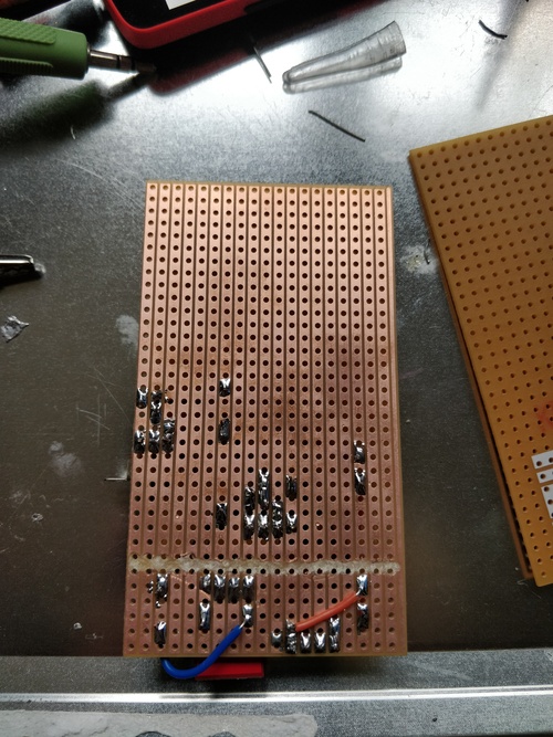
You can see a 4-pin header at the bottom. I put this there so I can plug it into a base board that has an
audio input and output jack, as wel as a switch to switch between the original audio signal and the filtered
signal.
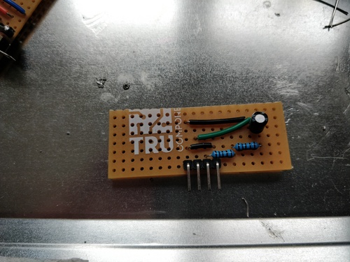
After putting it all together it worked! However, I didn't like the lowpass filter to be that big but only
using a small portion of the stripboard, So I cut off the top part and sanded it down, making it look much
smaller:
And here is the finished board with the lowpass filter:
And finally, a video showing the filter working with the output signal hooked up to my oscilloscope:
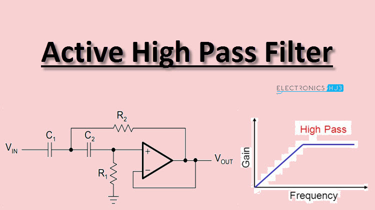
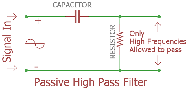
This article explains a lot about how
high pass filters work and why they work. Some notes about active high pass filter circuits can also be found
here. High-pass filters work
almost the same as low-pass filters, as in they filter a specific frequency based on the values of its
resistors and capacitors. The circuit for a basic RC highpass filter is the same as one for a lowpass filter,
but the only difference is that the resistor and capacitor have been switched.
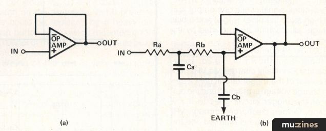
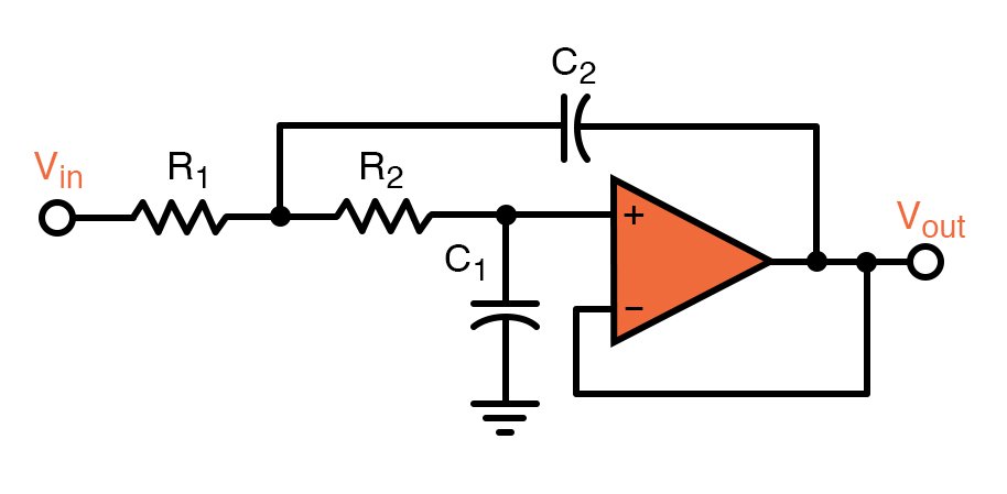
When I made the lowpass filter, I made it passive, and noticed that the sound coming out of it was pretty
quiet and hard to hear. So, I want to build an active high-pass filter circuit, with an op-amp to amplify the
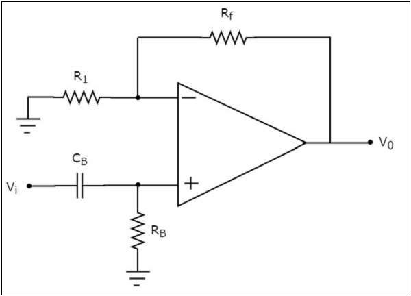
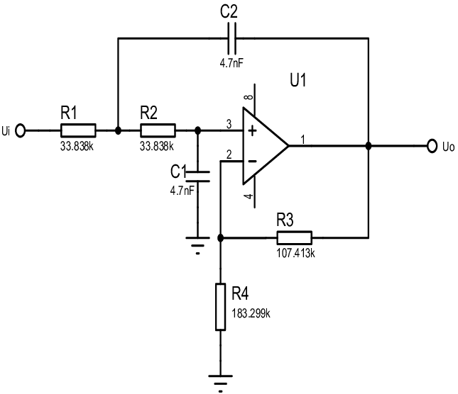
sound signal. The circuit I will make is a simple high-pass filter circuit with a non-inverting amplifier
circuit:
The voltage gain AV of the amplifier can be calculated with the formula AV = 1 + (R2
/ R1). Because I will need to use a small capacitor, I first had to find out how to read capacitor values. For the active circuit, I
used a TL072CP op-amp for the circuit. The
pinout is this:
I used a value of 22 Ohm for the resistor for the highpass filter, and a value of 2.2 uF for the capacitor.
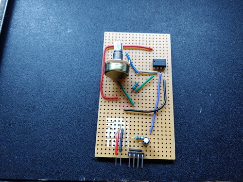
This makes the cutoff frequency fc = 1 / (2pi * 22 * 2.2e-6) = 3288.33 Hz. I first made just
the highpass filter with the resistor and the capacitor:
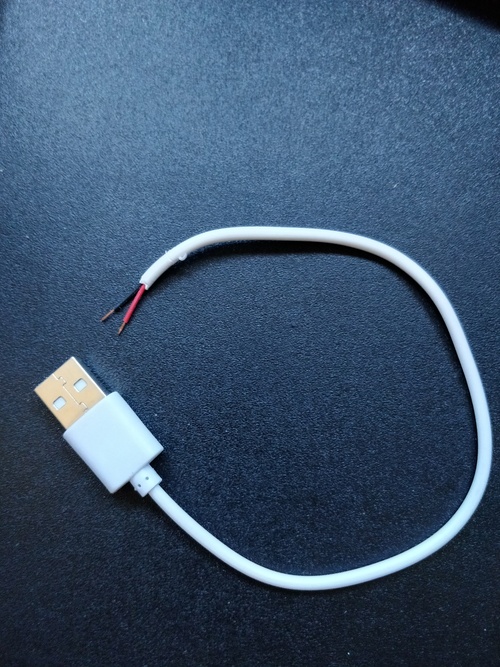
To supply power for the amplifier, I used an old cut-off USB cable I had lying around:
I tested it the same way I tested the lowpass filter. I hooked the filter up to
my oscilloscope and measured the original signal and the filtered signal. The filter can be seen working in
the video below. As the frequency decreases, the amplitude also decreases. The original signal is the top signal on the scope and the bottom signal is the filtered signal.
After that, I incorporated the TL072 op-amp into the breadboard circuit to amplify the filtered signal. I originally used values R1 = R2 = 2200 Ohm.
And it worked! The output signal was louder than before, but I noticed that the bottom half of the signal got cutoff. Then I realised this was because the input voltage to the amplifier comes from an USB port, so it was only +5V. This particular amplifer actually requires positive and negative voltage inputs. But because I didn't have any power supply that could generate this kind of voltage, I decided to just roll with it. I also wanted to be able to change the gain of the amplifier, so I replaced R2 with a 1K potentiometer and made R1 1K ohm.
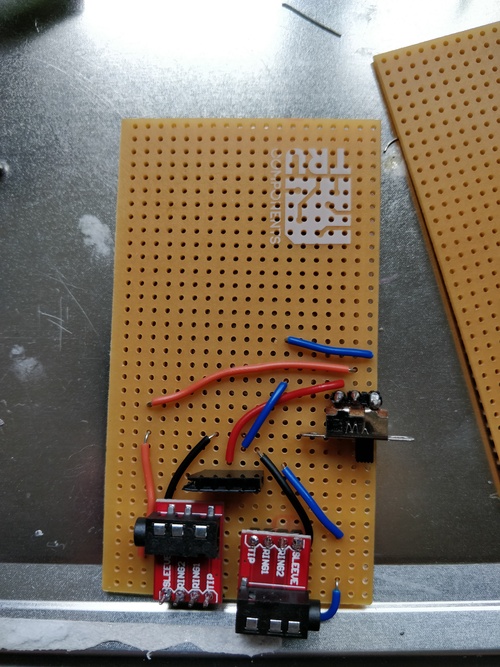
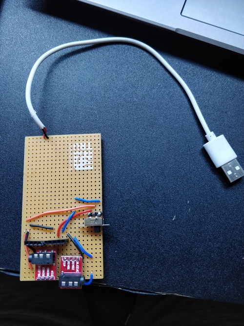
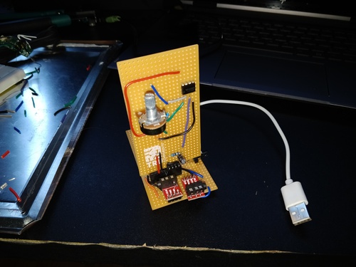
After that, I started working on soldering the filter to a piece of stripboard so that it could be plugged into the base filter board. I first added the USB cable to the base board, together with some more female pin headers:
Then, I built the stripboard version of the filter. I didn't have any right angle headers left, so I just used two pieces of wire.: