

Software
Set wifi on raspberry pi from SD card: add this to /boot/wpa_supplicant.conf:
            country=NL # Your 2-digit country code
            ctrl_interface=DIR=/var/run/wpa_supplicant GROUP=netdev
            network={
              ssid="YOUR_NETWORK_NAME"
              psk="YOUR_PASSWORD"
              key_mgmt=WPA-PSK
            }
Verbinding
control pixhawk met rpi:
- can pixhawk 4 be controlled by a companion computer?
- Via TELEM1, TELEM2, UART4 (bron)
- reddit: control pixhawk 4 with raspberry pi
- set up MAVLink on a serial port docs
- De MAV_X_MODE moet op Onboard staan voor communicatie met companion computer
- voorbeeld voor companion computer aansluting is hier te vinden
- [VIDEO] Make Your Own Pixhawk Raspberry Pi Drone in 36 Minutes
- TELEM1 of TELEM/SERIAL4 (UART/I2CB) aan UART raspberry pi, aan AMA0 serial port (GPIO UART pins)
- [VIDEO] Connect a Raspberry Pi to a Pixhawk running Ardupilot/PX4
- [VIDEO] Connecting Raspberry Pi w/ Pixhawk and Communicating via MAVLink Protocol
- RPI krijgt power van PDB, niet van pixhawk.
- Using a companion computer with pixhawk controllers
Mavlink op rpi:
Ardupilot op drone aansturen met python: dronekit python api
PX4 op drone aansturen met software: MAVSDK (verschillende versies, Python ). Op de PX4 wiki is ook een artikel te vinden over using a companion computer with pixhawk controllers (meer info: Companion Computers).
MAVlink documentation
Je kunt ook een drone simuleren met [VIDEO] SITL. (Deze video gebruikt mavproxy)
PX4 gebruikt uORB messaging om
berichten te
sturen. Dit is een publish() en subscribe() protocol. Er is een tutorial voor hoe je dit in
C++
kan doen. ROS2
is nog wel under development.
Pixhawk 4 Mini heeft maar 1 telemetry port (TELEM1), om de functie hiervan aan te passen
kan je de Serial
Port Configuration gebruiken. De Pi kan ook aan de TELEM/SERIAL4 port
New raspberry Pi with 8GB of RAM
Nieuwe raspberry pi met 8GB ram besteld omdat het builden van de px4_ros_com niet lukte met 2gb. Hierna werkte het wel gelijk
5G dongle
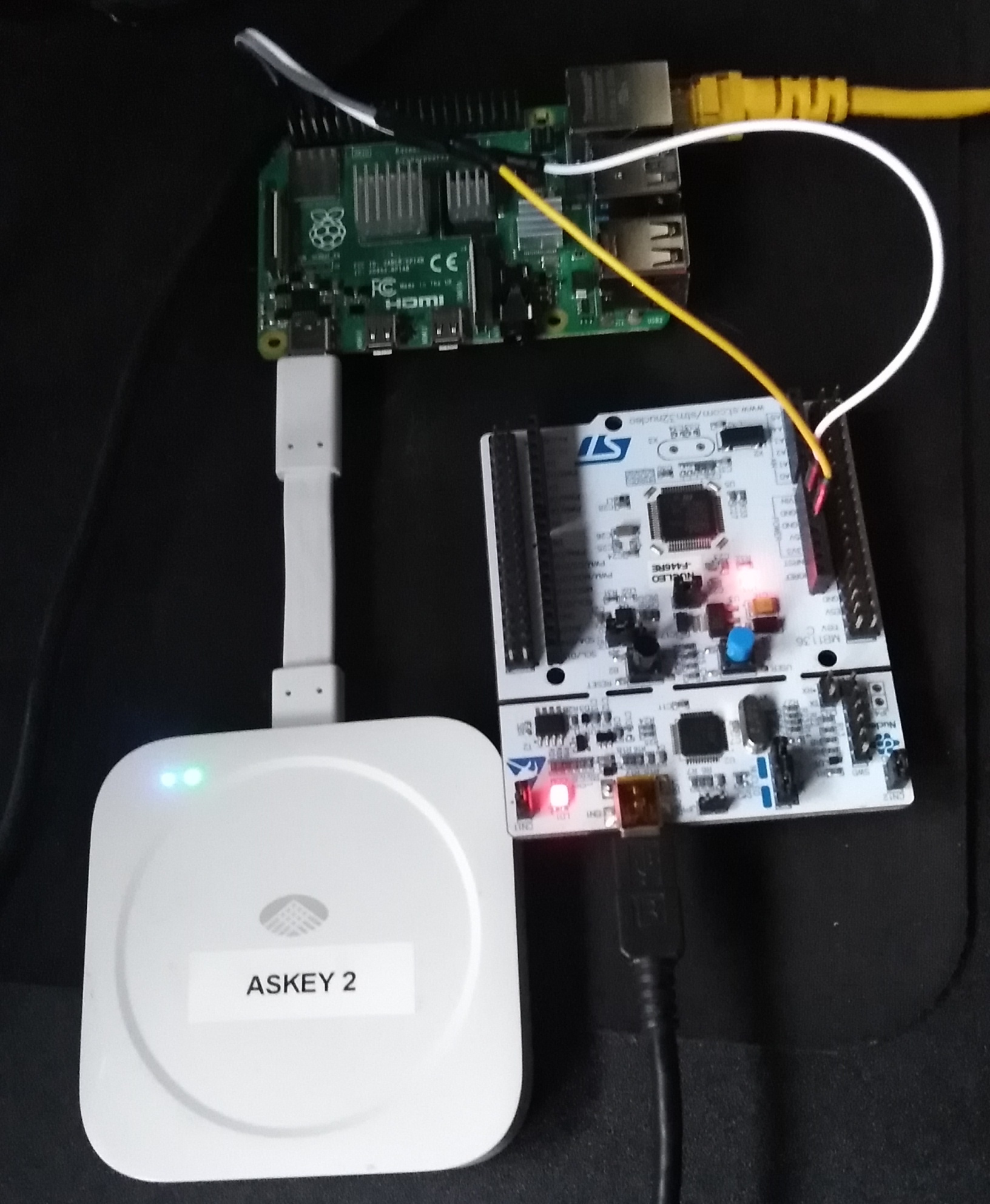
Link: Askey 5G NR USB dongle
use raspberry pi usb c port as host
config.txt on ubuntu is in /boot/firmware/
When attaching with usb to usb c dongle:
Bus 003 Device 001: ID 1d6b:0002 Linux Foundation 2.0 root hub
Bus 002 Device 001: ID 1d6b:0003 Linux Foundation 3.0 root hub
Bus 001 Device 004: ID 05c6:9057 Qualcomm, Inc. SDXPRAIRIE-MTP _SN:0FCDAC25
Bus 001 Device 002: ID 2109:3431 VIA Labs, Inc. Hub
Bus 001 Device 001: ID 1d6b:0002 Linux Foundation 2.0 root hub
Used the fix from here, the line to
change was dtoverlay=dwc2,dr_mode=host. The raspberry config file is located here. After that, usb output when powered with 5V line and 5G modem
attached with dongle:
ubuntu@raspberrypi-5g-drone:~$ lsusb
Bus 003 Device 002: ID 05c6:9057 Qualcomm, Inc. SDXPRAIRIE-MTP _SN:0FCDAC25
Bus 003 Device 001: ID 1d6b:0002 Linux Foundation 2.0 root hub
Bus 002 Device 001: ID 1d6b:0003 Linux Foundation 3.0 root hub
Bus 001 Device 002: ID 2109:3431 VIA Labs, Inc. Hub
Bus 001 Device 001: ID 1d6b:0002 Linux Foundation 2.0 root hub
When disconnecting and reconnecting the modem, the output is this:
[  703.735276] usb 3-1: USB disconnect, device number 2
[  703.735551] rndis_host 3-1:1.0 enxa49733070111: unregister 'rndis_host' usb-fe980000.usb-1, RNDIS device
[  716.835194] usb 3-1: new high-speed USB device number 3 using dwc2
[  717.156418] usb 3-1: New USB device found, idVendor=18d1, idProduct=d00d, bcdDevice= 1.00
[  717.156456] usb 3-1: New USB device strings: Mfr=1, Product=2, SerialNumber=3
[  717.156473] usb 3-1: Product: Android
[  717.156487] usb 3-1: Manufacturer: Google
[  717.156500] usb 3-1: SerialNumber: fcdac25
[  719.359444] usb 3-1: USB disconnect, device number 3
[  735.263348] usb 3-1: new high-speed USB device number 4 using dwc2
[  735.474230] usb 3-1: New USB device found, idVendor=05c6, idProduct=9057, bcdDevice= 4.14
[  735.474264] usb 3-1: New USB device strings: Mfr=1, Product=2, SerialNumber=3
[  735.474280] usb 3-1: Product: SDXPRAIRIE-MTP _SN:0FCDAC25
[  735.474294] usb 3-1: Manufacturer: QCOM
[  735.474307] usb 3-1: SerialNumber: fcdac25
[  735.486798] rndis_host 3-1:1.0 eth1: register 'rndis_host' at usb-fe980000.usb-1, RNDIS device, a4:97:33:07:01:11
[  735.594839] rndis_host 3-1:1.0 enxa49733070111: renamed from eth1
at 703 the modem is unplugged, at 716 it's plugged back in and recognized
as a Google Android device, but lsusb doesn't yet show anything. At 735
it's recognized again as a QCom device and then lsusb does recognize it.
The modem is recognised as a RNDIS device. It gets
assigned the eth1 interface, but that changes to enxa49733070111. When running the command
ifconfig enxa49733070111, the output is:
ubuntu@raspberrypi-5g-drone:~$ ifconfig enxa49733070111
enxa49733070111: flags=4098<BROADCAST,MULTICAST>  mtu 1500
        ether a4:97:33:07:01:11  txqueuelen 1000  (Ethernet)
        RX packets 0  bytes 0 (0.0 B)
        RX errors 0  dropped 0  overruns 0  frame 0
        TX packets 0  bytes 0 (0.0 B)
        TX errors 0  dropped 0 overruns 0  carrier 0  collisions 0
Laatste regel config.txt aangepast naar:
	dtoverlay=dwc2,dr_mode=host
	dtoverlay=disable-bt
Installing Ubuntu Server 22.04
Ik heb deze tutorial gevolgd en Ubuntu Server 22.04.1 LTS geïnstalleerd.
Preparing the SD card:
change ownership:
sudo chown sem:sem /dev/mmcblk0
Daarna bij schrijven error dat de FAT32 partition niet gemount kon worden, opgelost door eerst 0 te schrijven
sudo dd if=/dev/zero of=/dev/mmcblk0 bs=8192
dd: error writing '/dev/mmcblk0': No space left on device
1944769+0 records in
1944768+0 records out
15931539456 bytes (16 GB, 15 GiB) copied, 1219,99 s, 13,1 MB/s
Setting up the Linux installation:
Dit werkte, daarna ingelogd met default username:password ubuntu:ubuntu.
[$ | ~ (4) > ssh ubuntu@10.10.10.24
ubuntu@10.10.10.24's password:
Welcome to Ubuntu 22.04.1 LTS (GNU/Linux 5.15.0-1012-raspi aarch64)

 * Documentation:  https://help.ubuntu.com
 * Management:     https://landscape.canonical.com
 * Support:        https://ubuntu.com/advantage

  System information as of Thu Feb 16 13:39:31 UTC 2023

  System load:  0.17333984375      Temperature:           44.8 C
  Usage of /:   15.7% of 14.28GB   Processes:             141
  Memory usage: 12%                Users logged in:       1
  Swap usage:   0%                 IPv4 address for eth0: 10.10.10.24


0 updates can be applied immediately.


The list of available updates is more than a week old.
To check for new updates run: sudo apt update

Last login: Thu Feb 16 13:38:20 2023
To run a command as administrator (user "root"), use "sudo ".
See "man sudo_root" for details.
Pi geüpdate en geüpgrade.
Wifi ingesteld via deze
tutorial.
Ook static
IP ingesteld. De local IP was 10.1.1.68, en daar heb ik hem ook op
vastgezet.
Ik heb /etc/netplan/50-cloud-init.yaml aangepast naar:
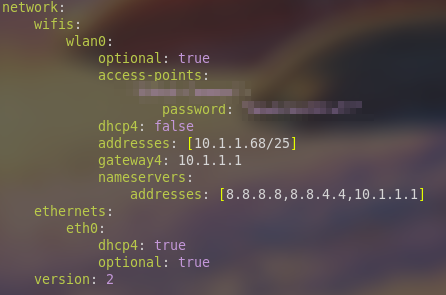
The config.txt is available here and here.
I installed Ubuntu 20.04 after building the PX4-ROS 2 bridge failed.
setting up the display
I connected the 4 inch HDMI display to the pi. Tutorial for writing to display without desktop environment The tutorial links to this blogpost about querying the framebuffer. I tried to install LXDE but got an error stating the session could not be started. this post explains the fix.
Settings for Ubuntu 20.04
Installing raspi-config didn't work, so I used this post to disable serial login and bluetooth.
connecting to the flight controller
I connected the rpi and pixhawk physically. Then I executed the command
mavproxy.py --master=/dev/serial0 --baudrate=57600 to start the connection. When trying
to arm, I got an error on QGroundControl  .
.
ubuntu@ubuntu:~$ mavproxy.py --master=/dev/serial0 --baudrate=57600
Connect /dev/serial0 source_system=255
Log Directory:
Telemetry log: mav.tlog
Waiting for heartbeat from /dev/serial0
MAV> Detected vehicle 1:1 on link 0
online system 1
MANUAL> Mode MANUAL
fence breach
Received 874 parameters
Saved 875 parameters to mav.parm

MANUAL>
MANUAL> arm throttle
MANUAL> Got COMMAND_ACK: COMPONENT_ARM_DISARM: TEMPORARILY_REJECTED
AP: Arming denied! manual control lost
I replied to a question on the PX4 forums where someone asked how to take off without RC. I also made a topic on the forum asking if anyone can help.
I also found this issue regarding the problem.
Hardware
Voor pi aan pixhawk is een JST-GH 6 pin to jumper wires connector nodig. Er is er een nodig voor UART & I2C en eentje voor TELEM1. Ik heb female jumper wires besteld die ik aan de bijgeleverde kabeltjes kan solderen.
connectie van pixhawk naar rpi (gwn met uart):
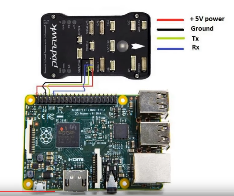
Connectie gemaakt van pixhawk naar pi. Pinout:
| pixhawk | raspi |
|---|---|
| VCC | 5V |
| TX | RXD (GPIO15) |
| RX | TXD (GPIO14) |
| GND | GND |
De volgorde van aansluitingen:
VCC niks POWER_GND RX TX niks PX4_GND
PilotPi is een shield en software om autopilot op de rpi uit te voeren. Dit is niet nodig voor ons omdat we de pixhawk hebben.
Connectors aan elkaar gesoldeerd in testing esc motors
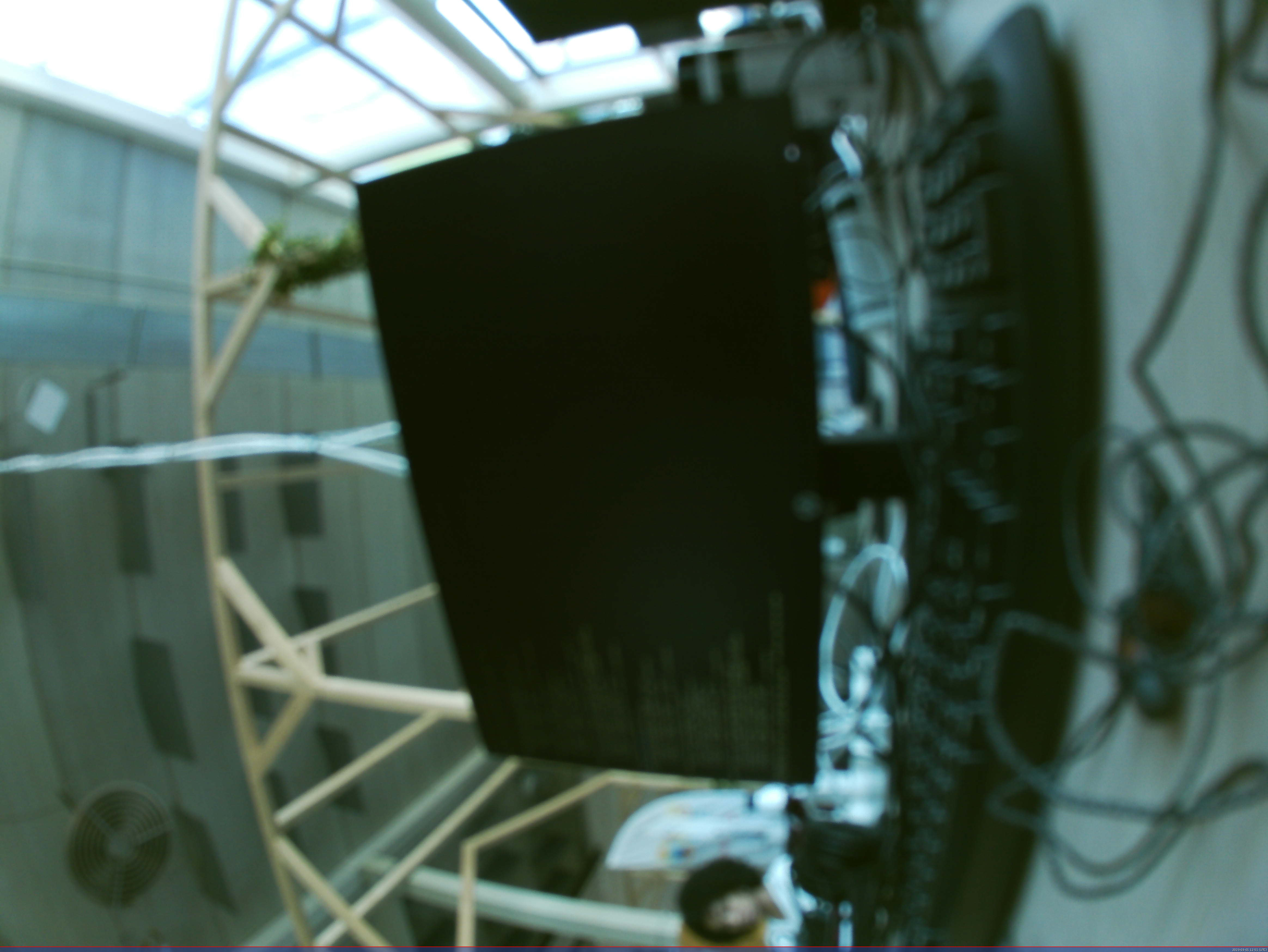
Foto test van camera
met fswebcam -r 4656x3496 web-cam-shot.jpg:
Voor ROS 2 is een camera node. You can use the image_tools package.
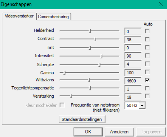
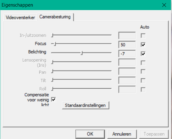
Camera ingesteld via windows 10 VM. De camera kan in 4K resolutie maar met 10 FPS filmen
Camera node gemaakt met OpenCV2, alleen dan kan ik geen 4k resolutie selecteren.
Python sockets video versturen
Testing the TeraRanger Evo Height Sensor and Multiflex Object detection sensor
I used this video and tried this example to test if the sensor works, the results were positive:
ubuntu@raspberrypi-5g-drone:~/teraranger_evo_mini/Python$ python3 Evo_Mini_py3.py
Evo Eco found on port /dev/ttyACM0
Sensor succesfully switched to binary mode
Sensor succesfully switched to long range measurement
Sensor succesfully switched to single range measurement
[-inf]
[0.093]
[0.094]
[0.092]
[0.1]
[0.099]
[0.097]
[0.096]
[0.094]
[0.088]
[0.089]
[0.096]
[0.095]
[0.104]
[0.104]
[0.109]
Er is een ROS node voor de TeraRanger Evo Mini, maar dit is voor ROS 1.
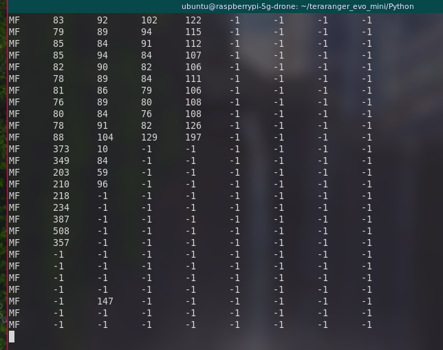
Ik heb de TeraRanger Multiflex getest en deze werkt ook. Ik heb de 1e 4 aangesloten:
Testing the TeraBee Tower Evo LiDar
TeraBee heeft een Sensor API om met al hun sensoren te interfacen.
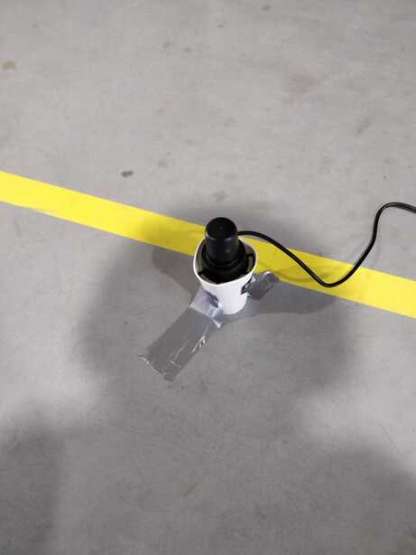
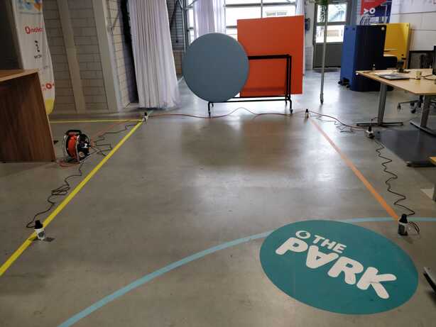
Testing the beacons Robot Positioning System
I tested the setup according to the user guide, with the AAP mode. This didn't work because the power adapters couldn't all get powered. I did configure all the anchors and trackers with the following info:
Anchors:
- AAP mode on
- z position 50 mm
- LED mode on
- priority x for anchor Ax
- short message mode
- LED mode on
- priority x for tracker Tx
- long message mode
Relais
Pi would not boot with Pixhawk connected to uart, solution is here. Fixed by putting relais in between RX and TX pins and turning on after pi has booted.
relais_controller.py:
import rclpy
from rclpy.node import Node

try:
    import RPi.GPIO as GPIO
except RuntimeError:
    print("Error importing RPi.GPIO!  This is probably because you need superuser privileges.  You can achieve this by using 'sudo' to run your script")

from drone_services.srv import ControlRelais
class RelaisController(Node):
    def __init__(self):
        super().__init__('relais_controller')
        self.srv = self.create_service(ControlRelais, '/drone/control_relais', self.control_relais_callback)

        self.relais1_pin = 17
        self.relais2_pin = 27
        self.init_gpio()
        self.turn_relais_on()

    def init_gpio(self):
        GPIO.setwarnings(False)

        self.get_logger().info(str(GPIO.RPI_INFO))

        GPIO.setmode(GPIO.BCM)

        GPIO.setup(self.relais1_pin, GPIO.OUT)
        GPIO.setup(self.relais2_pin, GPIO.OUT)
        self.get_logger().info("GPIO initialized")

    def turn_relais_on(self):
        GPIO.output(self.relais1_pin, GPIO.HIGH)
        GPIO.output(self.relais2_pin, GPIO.HIGH)
        self.get_logger().info("Relais turned on")

    def control_relais_callback(self, request, response):
        if request.relais1_on:
            GPIO.output(self.relais1_pin, GPIO.HIGH)
            response.bits = response.bits | 1
        else:
            GPIO.output(self.relais1_pin, GPIO.LOW)
            response.bits = response.bits & ~(1 << 0)
        if request.relais2_on:
            GPIO.output(self.relais2_pin, GPIO.HIGH)
            response.bits = response.bits | (1 << 1)
        else:
            GPIO.output(self.relais2_pin, GPIO.LOW)
            response.bits = response.bits & ~(1 << 1)
        return response

def main(args=None):
    rclpy.init(args=args)

    relais_controller = RelaisController()

    rclpy.spin(relais_controller)

    # Destroy the node explicitly
    # (optional - otherwise it will be done automatically
    # when the garbage collector destroys the node object)
    relais_controller.destroy_node()
    rclpy.shutdown()


if __name__ == '__main__':
    main()
Optical flow sensor
GPS works but not great, ordered a optical flow sensor for indoor positioning
Sensor: Here Flow
- uses an PWM3901 sensor
- documentation