Vervolgens ben ik begonnen om een driver te schrijven voor de ADXL345 versnellingsmeter. Om de
versnellingsmeter goed uit te kunnen lezen heb ik eerst een header file ADXL345.h geschreven:
/*
* ADXL345.h
*
*  Created on: Sep 21, 2021
*      Author: Sem
*/

#ifndef ADXL345_H_
#define ADXL345_H_

#include < string.h >
#include < stdio.h >
#include "main.h"

#define ADXL345_DEFAULT_SCALE_FACTOR 0.078


typedef enum { //addresses, refer to datasheet for reference.
ALT_LOW_READ = 0xA7,		// alt address pin low, read
ALT_LOW_WRITE = 0xA6,		// alt address pin low, write
ALT_HIGH_READ = 0x3B,		// alt address pin high, read
ALT_HIGH_WRITE = 0x3A		// alt address pin high, write
} ADXL345_ADDRESS;

typedef enum {
LOW,						// alt address pin low
HIGH						// alt address pin high
}ADXL345_ALT_PIN;

typedef struct {
I2C_HandleTypeDef *i2c_handle;		// handle to i2c peripheral
UART_HandleTypeDef *uart_handle;	// handle to uart peripheral
ADXL345_ALT_PIN alt_pin;			// enum to determine address when reading or writing
float scale_factor;					// g value scale factor
float x_offset;						// x g value offset
float y_offset;						// y g value offset
float z_offset;						// z g value offset
} ADXL345_t;


/**
* @brief initializes the offset and scale factor values of the accelerometer,
* make sure the accelerometer is flat when this is called.
* @param adxl the struct holding the accelerometer value
* @ret status code that indicates if an error occurred.
*/
HAL_StatusTypeDef ADXL345_calculate_offsets(ADXL345_t *adxl);

/**
* @brief initializes the accellerometer
*
* @param adxl the struct holding the accelerometer info
* @ret status code that inidcates if the initialising worked
*/
HAL_StatusTypeDef ADXL345_init(ADXL345_t *adxl);

/**
* @brief reads the x, y and z value from the acceleration sensor
*
* @param adxl the struct holding the accelerometer info
* @param huart2 the uart handle
* @param result_arr an array of 3 floats to hold the resulting values
*
* @ret status code of HAL_OK if there was no error, otherwise statuscode of resulted error.
*/
HAL_StatusTypeDef ADXL345_read(ADXL345_t *adxl, float *result_arr);


#endif /* ADXL345_H_ */
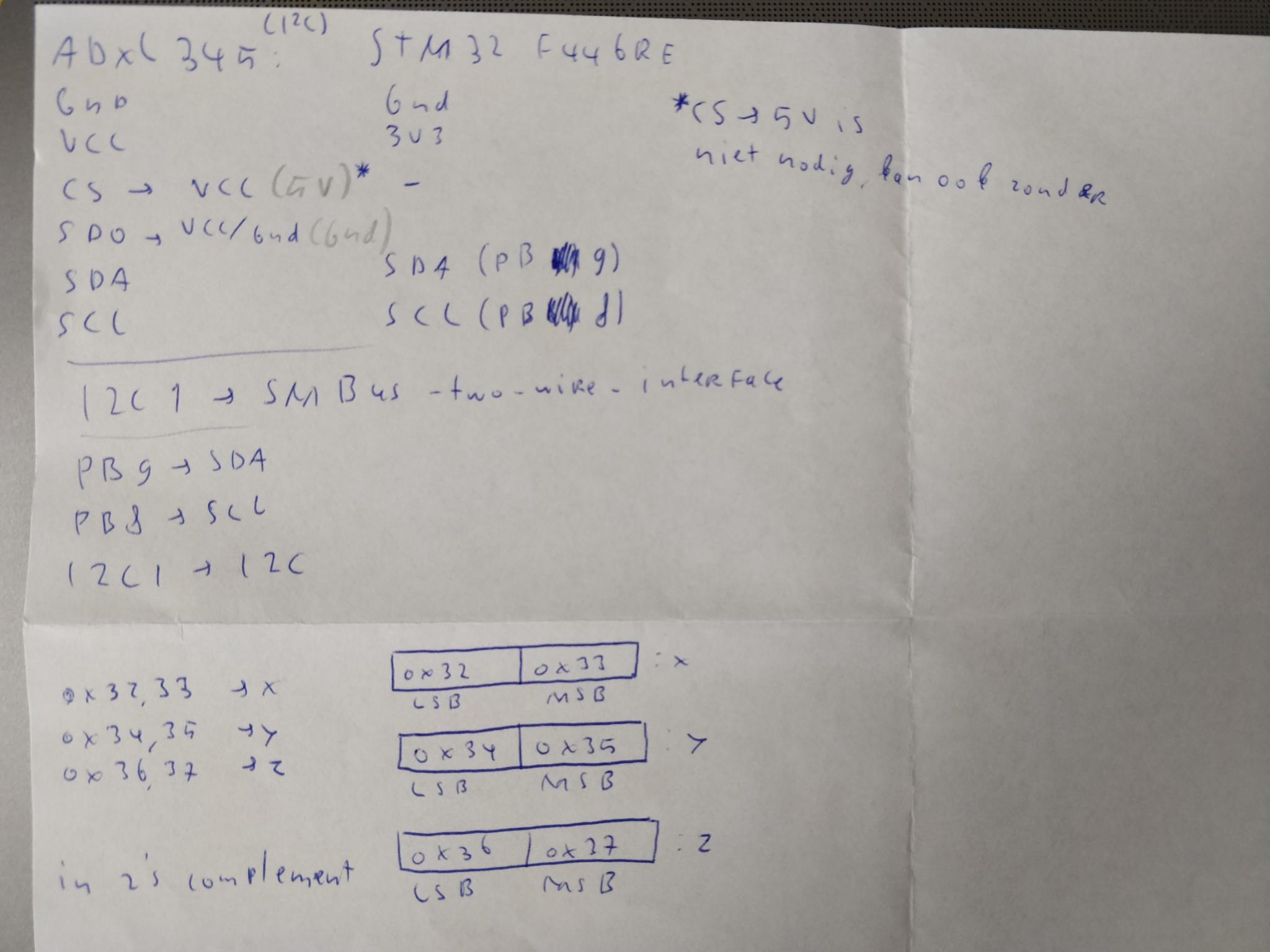
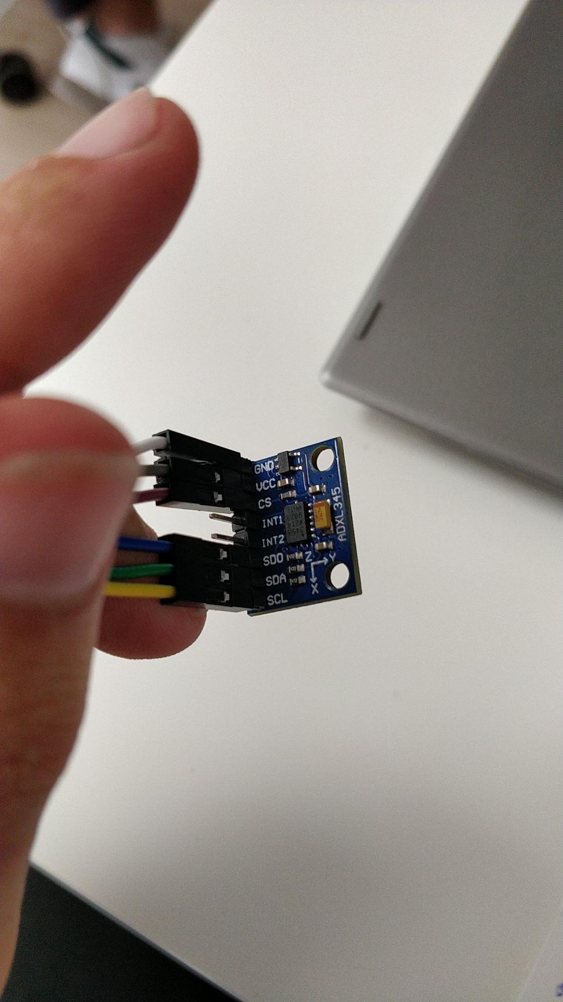
Deze header file bevat een enum die de verschillende adressen bevat om naar en van de
versnellingsmeter te schrijven en lezen. Het bevat ook een enum om aan te geven of de
ALT_ADDRESS pin van de versnellingsmeter hoog of laag staat. Het bevat bovendien een struct
die alle benodigde variabelen bevat om de versnellingsmeter aan te sturen. Hierin zit een handle
naar de I²C peripheral, een handle naar de UART peripheral, een variabele van de enum die aangeeft
of de ALT_ADDRESS pin hoog of laag staat, een scale factor voor de g waarde en offsets voor de x, y
en z waarden. De header file bevat ook de functie ADXL345_calculate_offsets waarmee de scale factor en de
individuele offsets voor de 3 assen worden berekend. Met de functie ADXL345_init worden de registers van de versnellingsmeter
gereset en ingesteld. Met de functie ADXL345_read kunnen de
3 waarden van de assen gelezen worden.
De definitie van de functies is als volgt:
/*
* ADXL345.c
*
*  Created on: Sep 21, 2021
*      Author: Sem
*/

#include "ADXL345.h"

//I2C: 0 = write, 1 = read

/**
* @brief performs a sign extension on the given input number
* @param smallInt the 2s complement integer to perform the sign extension on
* @retval bits the amount of bits in the number
*/
void sign_extension(int *smallInt, char bits)
{
const int negative = (*smallInt & (1 << (bits - 1))) != 0; // check if number is negative

if (negative)
*smallInt = *smallInt | ~((1 << bits) - 1);	// if number is negative, convert it
}

HAL_StatusTypeDef ADXL345_calculate_offsets(ADXL345_t *adxl)
{

HAL_StatusTypeDef ret;		// status code return value

// check if the alt address pin is low or high
uint16_t addr = adxl->alt_pin == LOW ? ALT_LOW_READ : ALT_HIGH_READ;

int x = 0, y = 0, z = 0;	// values of axes
char buf[40];				// buffer for uart
char i2c_return_data[6];	// buffer to hold return data

// first, get the first 1000 reads and calculate the mean scale factor
for (int i = 0; i < 1000; i++)
{
// i2c read the values of the accelerometer
ret = HAL_I2C_Mem_Read(adxl->i2c_handle, addr, 0x32, 1,
        (uint8_t*) i2c_return_data, 6,
        HAL_MAX_DELAY);

// check if an error occurred, if so, return
if (ret != HAL_OK)
{
    sprintf(buf, "error %x", ret);
    UART_send(buf);
    return ret;
}

z = ((i2c_return_data[5] << 8) | i2c_return_data[4]);// get the z value
sign_extension(&z, 16);	// perform sign extension to turn it into a decimal int
adxl->scale_factor += (9.81 / z);// devide it by 9.81 (g of earth) and add it to
                                 //the scale factor of the accellerometer
}

adxl->scale_factor /= 1000.0;	// calculate the mean scale factor

// calculate the mean offsets for x, y and z
// read the values 1000 times
for (int i = 0; i < 1000; i++)
{
// i2c read of the values of the axes
ret = HAL_I2C_Mem_Read(adxl->i2c_handle, addr, 0x32, 1,
        (uint8_t*) i2c_return_data, 6,
        HAL_MAX_DELAY);

// check if an error occurred, if so, report and return
if (ret != HAL_OK)
{
    sprintf(buf, "error %x", ret);
    UART_send(buf);
    return ret;
}

// get all the values
x = ((i2c_return_data[1] << 8) | i2c_return_data[0]);
y = ((i2c_return_data[3] << 8) | i2c_return_data[2]);
z = ((i2c_return_data[5] << 8) | i2c_return_data[4]);

// perform sign extension on all values to get decimal
sign_extension(&x, 16);
sign_extension(&y, 16);
sign_extension(&z, 16);

// multiply by scale factor and add to offsets
float xf = x * adxl->scale_factor;
float yf = y * adxl->scale_factor;
float zf = z * adxl->scale_factor;
adxl->x_offset += xf;
adxl->y_offset += yf;
adxl->z_offset += 9.81 - zf;
}

// calculate mean offsets
adxl->x_offset /= 1000.0;
adxl->y_offset /= 1000.0;
adxl->z_offset /= 1000.0;
return HAL_OK;
}

HAL_StatusTypeDef ADXL345_init(ADXL345_t *adxl)
{

HAL_StatusTypeDef ret;	//status code return value

// check if the alt address pin is high or low
uint16_t addr = adxl->alt_pin == LOW ? ALT_LOW_READ : ALT_HIGH_READ;

char data_to_send[1];	// array to hold data to send over i2c
char buf[40];			// buffer for uart

// reset all bits
ret = HAL_I2C_Mem_Write(adxl->i2c_handle, addr, 0x2D, 1, 0x00, 1,
HAL_MAX_DELAY);

// check if error occurred, if so, return it
if (ret != HAL_OK)
{
sprintf(buf, "error %x", ret);
UART_send(buf);
return ret;
}
// set POWER_CTL register:
// link bit = 0
// auto_sleep bit = 0
// measure bit = 1
// sleep bit = 0
// wakeup bits = 00 (8Hz)
data_to_send[0] = 0b00001000;

// send data
ret = HAL_I2C_Mem_Write(adxl->i2c_handle, addr, 0x2D, 1,
    (uint8_t*) data_to_send, 1,
    HAL_MAX_DELAY);

// check if error occurred, if so, return it
if (ret != HAL_OK)
{
sprintf(buf, "error %x", ret);
UART_send(buf);
return ret;
}

// set DATA_FORMAT bits
// self test = 0
// spi = 0
// int_invert = 0
// d4 = 0
// full_res = 0 (10 bit resolution)
// justify = 0 (right justified)
// range = 01 (+/- 4g)
data_to_send[0] = 0b00000001;

// send data
ret = HAL_I2C_Mem_Write(adxl->i2c_handle, addr, 0x31, 1,
    (uint8_t*) data_to_send, 1,
    HAL_MAX_DELAY);

// check if error occurred, if so, return it
if (ret != HAL_OK)
{
sprintf(buf, "error %x", ret);
UART_send(buf);
return ret;
}

return HAL_OK;
}

HAL_StatusTypeDef ADXL345_read(ADXL345_t *adxl, float *result_arr)
{

HAL_StatusTypeDef ret;		// status code return value
uint8_t i2c_return_data[6]; // 6 bytes array to hold return value,
                        // first 2 bytes is x, next two bytes is y,
                        // last 2 bytes is z

char buf[30];				// buffer for uart
int x = 0, y = 0, z = 0;	// variables to hold data from accellerometer

// check if alt pin is low or high and set address accordingly
uint16_t addr = adxl->alt_pin == LOW ? ALT_LOW_READ : ALT_HIGH_READ;

// get x, y and z values and read them into the array
ret = HAL_I2C_Mem_Read(adxl->i2c_handle, addr, 0x32, 1,
    (uint8_t*) i2c_return_data, 6,
    HAL_MAX_DELAY);

// check if error occurred, if so, print over uart and return
if (ret != HAL_OK)
{
sprintf(buf, "error %x", ret);
UART_send(buf);
return ret;
}

// chop the values from the array
x = ((i2c_return_data[1] << 8) | i2c_return_data[0]);
y = ((i2c_return_data[3] << 8) | i2c_return_data[2]);
z = ((i2c_return_data[5] << 8) | i2c_return_data[4]);

// perform sign extension to convert to decimal
sign_extension(&x, 16);
sign_extension(&y, 16);
sign_extension(&z, 16);

// print raw values
//	sprintf(buf, "x: %d\ty: %d\tz: %d\r\n", x, y, z);
//	UART_send(buf);

// multiply by scale factor calculated beforehand
result_arr[0] = x * adxl->scale_factor;
result_arr[1] = y * adxl->scale_factor;
result_arr[2] = z * adxl->scale_factor;

return HAL_OK;
}
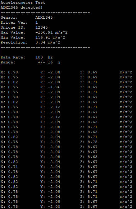
De output hiervan is als volgt:
Er is dus te zien dat de waarden kunnen worden uitgelezen
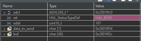
Hierna had ik echter een probleem: Als ik de code opnieuw uploadde, kreeg ik een 0x02, oftewel een HAL_BUSY statuscode terug. Dit was al bij de eerste keer dat er
een I²C aanroep werd gedaan:
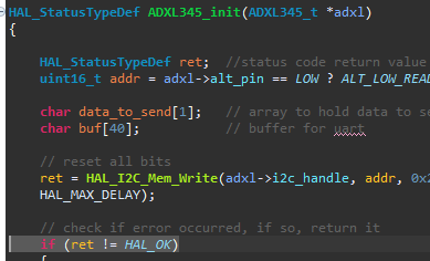
Bij de gemarkeerde regel had ik de debugger gestopt om te kijken wat de waarde van ret was, en deze was
HAL_BUSY (0x02):
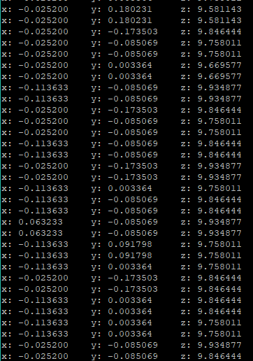
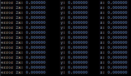
Deze statuscode werd elke keer gegenereerd als ik een I²C aanroep wilde doen. Dit is te zien aan de
output
die ik kreeg als deze statuscode teruggegeven werd:
Dit wilde ik eerst oplossen door deze statuscode af te vangen bij het initialiseren, en zo nodig een
aantal keer te proberen om de versnellingsmeter opnieuw te initialiseren:
// try to init, if it didn't work, try again a set number of times
HAL_StatusTypeDef ret = ADXL345_init(&adxl, 1);	// reset and init accellerometer
if (ret != HAL_OK)
{
	sprintf(buf,
			"There was an error initialising the i2c for ADXL345: 0x%02X\r\n",
			ret);
	UART_send(buf);

	for (uint8_t i = 0; i < ADXL345_I2C_RETRIES; i++)
	{
		sprintf(buf, "Trying to init again...\r\n");
		UART_send(buf);
		HAL_I2C_DeInit(&hi2c1);
		__HAL_RCC_I2C1_CLK_DISABLE();
		HAL_Delay(100);
		MX_I2C1_Init();
		ret = ADXL345_init(&adxl, 1);
		if (ret == HAL_OK)
		{
			sprintf(buf, "ADXL345 succesfully Initialised!\r\n");
			UART_send(buf);
			break;
		}
	}
}
Dit werkte soms, maar het was nog steeds niet consistent en dus nog niet betrouwbaar. Ik ben verder gaan
zoeken en ik vond deze
vraag op Stackoverflow. Deze persoon had hetzelfde probleem als ik. In het antwoord stond dat
dit een bug was in de software van het ontwikkelbord en dat in de Errata
sheet (pagina 24) een oplossing stond. Deze heb ik gevolgd en ik heb de functie HAL_StatusTypeDef I2C_clear_busy_bit_errata(I2C_HandleTypeDef *hi2c)
gemaakt. Deze functie is als volgt:
 /**
 * writes to the ODR of the specified GPIO pin
 */
void HAL_GPIO_WRITE_ODR(GPIO_TypeDef *GPIOx, uint16_t GPIO_Pin)
{
    /* Check the parameters */
    assert_param(IS_GPIO_PIN(GPIO_Pin));

    GPIOx->ODR |= GPIO_Pin;
}

/**
 * resets the i2c peripheral according to the errata sheet
 * solution from https://electronics.stackexchange.com/questions/272427/stm32-busy-flag-is-set-after-i2c-initialization
 * This is done because there is a glitch in the analog filter which continuously sets the i2c flag as busy
 */
HAL_StatusTypeDef I2C_clear_busy_bit_errata(I2C_HandleTypeDef *hi2c)
{

	GPIO_InitTypeDef GPIO_InitStruct;
	char buf[50];
	static uint8_t resetTried = 0;
	if (resetTried == 1)
	{
		sprintf(buf, "reset tried = 1\r\n");
		UART_send(buf);
		return HAL_ERROR;
	}

	sprintf(buf, "[INFO] clearing busy bit\r\n");
	UART_send(buf);

	// SDA = pin 9
	uint32_t SDA_PIN = GPIO_PIN_9;

	// SCL = pin 8
	uint32_t SCL_PIN = GPIO_PIN_8;

//	1. Disable the I2C peripheral by clearing the PE bit in I2Cx_CR1 register.
	__HAL_I2C_DISABLE(&hi2c1);

//	2. Configure the SCL and SDA I/Os as General Purpose Output Open-Drain, High level
//	(Write 1 to GPIOx_ODR).
	GPIO_InitStruct.Pin = SDA_PIN | SCL_PIN;
	GPIO_InitStruct.Mode = GPIO_MODE_OUTPUT_OD;
	GPIO_InitStruct.Pull = GPIO_NOPULL;
	GPIO_InitStruct.Speed = GPIO_SPEED_FAST;
	HAL_GPIO_Init(GPIOB, &GPIO_InitStruct);

	HAL_GPIO_WRITE_ODR(GPIOB, SDA_PIN);
	HAL_GPIO_WRITE_ODR(GPIOB, SCL_PIN);

//	3. Check SCL and SDA High level in GPIOx_IDR.

	if (GPIOB->IDR == GPIO_PIN_RESET)
	{
		sprintf(buf, "[ERROR] step 3: IDR level is low!\r\n");
		UART_send(buf);
		return HAL_ERROR;
	}

	if (HAL_GPIO_ReadPin(GPIOB, SCL_PIN) == GPIO_PIN_RESET)
	{
		sprintf(buf, "[ERROR] step 3: IDR SCL level is low!\r\n");
		UART_send(buf);
		return HAL_ERROR;
	}

	if (HAL_GPIO_ReadPin(GPIOB, SDA_PIN) == GPIO_PIN_RESET)
	{
		sprintf(buf, "[ERROR] step 3: IDR SDA level is low!\r\n");
		UART_send(buf);
		return HAL_ERROR;
	}
//	4. Configure the SDA I/O as General Purpose Output Open-Drain, Low level (Write 0 to
//	GPIOx_ODR).

	GPIO_InitStruct.Pin = SDA_PIN;
	HAL_GPIO_Init(GPIOB, &GPIO_InitStruct);
	HAL_GPIO_TogglePin(GPIOB, SDA_PIN);

//	5. Check SDA Low level in GPIOx_IDR.
	if (HAL_GPIO_ReadPin(GPIOB, SDA_PIN) == GPIO_PIN_SET)
	{
		sprintf(buf, "[ERROR] step 5: SDA level is high!\r\n");
		UART_send(buf);
		return HAL_ERROR;
	}
//	6. Configure the SCL I/O as General Purpose Output Open-Drain, Low level (Write 0 to
//	GPIOx_ODR).

	GPIO_InitStruct.Pin = SCL_PIN;
	HAL_GPIO_Init(GPIOB, &GPIO_InitStruct);
	HAL_GPIO_TogglePin(GPIOB, SCL_PIN);

//	7. Check SCL Low level in GPIOx_IDR.

	if (HAL_GPIO_ReadPin(GPIOB, SCL_PIN) == GPIO_PIN_SET)
	{
		sprintf(buf, "[ERROR] step 7: IDR SCL level is high!\r\n");
		UART_send(buf);
		return HAL_ERROR;
	}
//	8. Configure the SCL I/O as General Purpose Output Open-Drain, High level (Write 1 to
//	GPIOx_ODR).

	GPIO_InitStruct.Pin = SCL_PIN;
	HAL_GPIO_Init(GPIOB, &GPIO_InitStruct);

	GPIOB->ODR |= SCL_PIN;

//	9. Check SCL High level in GPIOx_IDR.
	if (HAL_GPIO_ReadPin(GPIOB, SCL_PIN) == GPIO_PIN_RESET)
	{
		sprintf(buf, "[ERROR] step 9: ODR SCL level is low!\r\n");
		UART_send(buf);
		return HAL_ERROR;
	}

//	10. Configure the SDA I/O as General Purpose Output Open-Drain , High level (Write 1 to
//	GPIOx_ODR).
	GPIO_InitStruct.Pin = SDA_PIN;
	HAL_GPIO_Init(GPIOB, &GPIO_InitStruct);

	GPIOB->ODR |= SDA_PIN;

//	11. Check SDA High level in GPIOx_IDR.
	if (HAL_GPIO_ReadPin(GPIOB, SDA_PIN) == GPIO_PIN_RESET)
	{
		sprintf(buf, "[ERROR] step 11: ODR SDA level is low!\r\n");
		UART_send(buf);
		return HAL_ERROR;
	}

//	12. Configure the SCL and SDA I/Os as Alternate function Open-Drain.
	GPIO_InitStruct.Pin = SDA_PIN | SCL_PIN;
	GPIO_InitStruct.Mode = GPIO_MODE_AF_OD;
	GPIO_InitStruct.Alternate = GPIO_AF4_I2C1;
	HAL_GPIO_Init(GPIOB, &GPIO_InitStruct);

//	13. Set SWRST bit in I2Cx_CR1 register.
	hi2c->Instance->CR1 |= I2C_CR1_SWRST;

//	14. Clear SWRST bit in I2Cx_CR1 register.
	hi2c->Instance->CR1 ^= I2C_CR1_SWRST;

//	15. Enable the I2C peripheral by setting the PE bit in I2Cx_CR1 register.
	__HAL_I2C_ENABLE(hi2c);

	sprintf(buf, "[INFO] cleared busy bit!\r\n");
	UART_send(buf);

	resetTried = 1;
	return HAL_OK;
}
Dit heb ik hierna verwerkt in het stukje om de sensor opnieuw te calibreren:
HAL_StatusTypeDef ret = ADXL345_init(&adxl, 1);	// reset and init accellerometer
if (ret != HAL_OK)
{
    sprintf(buf,
            "There was an error initialising the i2c for ADXL345: 0x%02X\r\n",
            ret);
    UART_send(buf);
    if (ret == HAL_BUSY)
        ret = I2C_clear_busy_bit_errata(&hi2c1);
    else
    {
        for (uint8_t i = 0; i < ADXL345_I2C_RETRIES; i++)
        {
            sprintf(buf, "Trying to init again...\r\n");
            UART_send(buf);
            HAL_I2C_DeInit(&hi2c1);
            __HAL_RCC_I2C1_CLK_DISABLE();
            HAL_Delay(100);
            MX_I2C1_Init();
            ret = ADXL345_init(&adxl, 1);
            if (ret == HAL_OK)
            {
                sprintf(buf, "ADXL345 succesfully Initialised!\r\n");
                UART_send(buf);
                break;
            }
        }
    }
}
Als ik de code nu uitvoer krijg ik de volgende output:
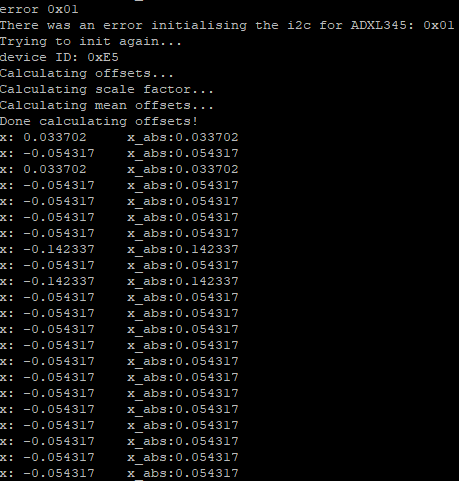
Er is dus te zien dat het opnieuw calibreren werkt. Ik kan nu de waarden van de versnellingsmeter via
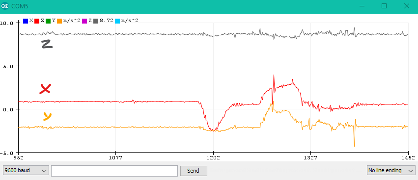
het STM32 ontwikkelbord uitlezen. Om de x-waarde weer tegeven heb ik deze in een grafiek uitgezet tegen
de tijd:
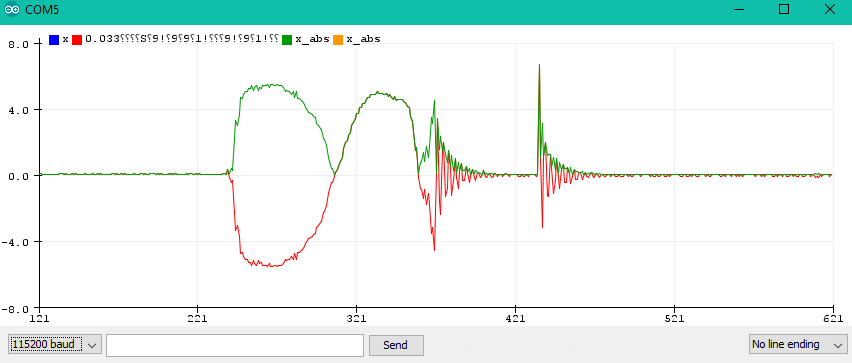
Tijdens het meten heb ik de vernelliingsmeter een aantal keer bewogen en dit is ook te zien in de
grafiek. Op de grafiek is de rode lijn de x waarde en de groene lijn is de absolute waarde van de x
waarde.